2013. augusztus 1., csütörtök

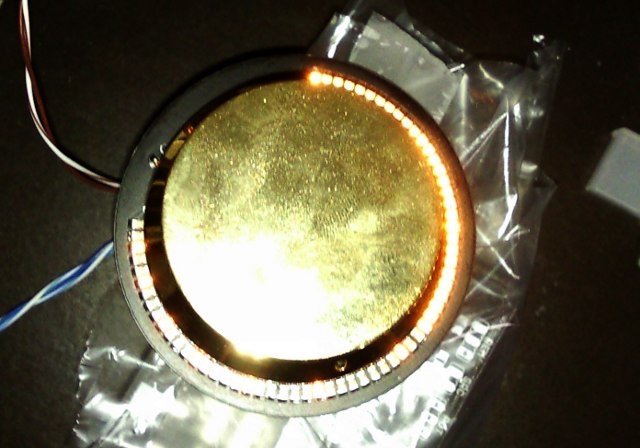
Using Arduino with the 8th note Stepped Attenuator

The gateway to external displays

This text is about how to use an Arduino to read data from the 8th note Stepped Attenuator.
The Arduino is an easy to use programmable hardware, wich is very popular amongst DIY-ers.
If you want to make an external display for your attenuator then this is where you must start.


What is possible?
There are digital ports on the driver board. Using these ports it is possible to read the following:
-is MUTE on?
-is LULO active?
-is SRC2 selected?
-what is the attenuation level?

What is it good for?
You can use these data to output text on a display, or make a led bar show the attenuation level, or do whatever you can think of to do with. You can find inspiring ideas in the last blog entry.

What skills are needed?
You need some experience in using Arduino and programming it. If you are not familiar with Arduino, then stop at Arduino's webpage first. There are many good articles to beginners, helpful communities, user forums and lots of example codes on the internet, which can help you in the first steps.
Because there are many infos out there about Arduino, I will not duplicate it here. This article will focus on helping users to write the 8th note specific part of their own program.

What will we do?
We will read the state of the MUTE, LULO and SRC2 LEDs, which is the simplest task. We will read the digital out (DO) port and decode the attenuation level.

Lets start it!
First you have to solder two unpopulated headers into the board. The one called DO (1x3 pin) and located on the bottom right corner of the driver board,
the other has no name and located next to the status LEDs (2x3 pins). We will use these headers or at least part of it.


The "LED header" (lets call it that way) contains pins to read the LEDs status.
You need to wire these pins to GPIO input pins:

You have to check these pins state on the Arduino, it has the value either HIGH or LOW. Choose pins that are not needed later for something else.
Please note, the pins status are LOW when the function (and its LED) is active.
The state of the pins can be read with the following (well known) way:

//let the pins connected to the following:
int mutePin = 7;
int luloPin = 8;
int src2Pin = 9;

//store the pin state in these variables
int mute_State = 0;
int lulo_State = 0;
int src2_State = 0;

void setup()
{
  pinMode(mutePin, INPUT);      // sets the digital pin as input
  pinMode(luloPin, INPUT);      // sets the digital pin as input
  pinMode(src2Pin, INPUT);      // sets the digital pin as input
}

void loop()
{
  mute_State = digitalRead(mutePin);   // read the input pin
  lulo_State = digitalRead(luloPin);   // read the input pin
  src2_State = digitalRead(src2Pin);   // read the input pin
}

Now if you have the variables then you can change your display according to it.

This was the easy part.

How to get the attenuation level?
The attenuation level can be read on the DO header of the driver board.
The DO port uses standard SPI communication. If you are not familiar with SPI, then follow this link to the Arduino SPI reference:
http://arduino.cc/en/Reference/SPI

A short quote from it:
"Serial Peripheral Interface (SPI) is a synchronous serial data protocol used by microcontrollers for communicating with one or more peripheral devices quickly over short distances. It can also be used for communication between two microcontrollers."


This is what we will do.
The SPI protocol uses a Clock and a Serial data line. When the clock ticks, the serial line state in the receiver is stored in a register. When it ticks again, it stores the next value in the register, until 8 bits are received.


In our case, the Master (and transmitter) will be the 8th note Stepped Attenuator and the Slave (and receiver) will be the Arduino. The SPI protocol defines a Slave Select (SS) pin what we don't use, because we have only one slave.
The DO port has the SCK (serial clock), the MOSI (Master Out Slave In) and a GND (ground) pins.


Note that MOSI, and SCK are available in a consistent physical location on the Arduino's ICSP header. You need to wire these pins.

Arduino ICSP header pinout

When finished with the wiring, lets think a little together.
The following is important and specific to the 8th note Stepped Attenuator:
  • The attenuator transmits data only on state change, in other words, you can not request a transmission
  • The transmitted data consists of 16 bits or 2 bytes, and repeated once
  • The two byte long data can be decoded to return the attenuation level

The transmitted data bits are mixed for design reasons, and can be decoded in a quick function that returns a byte between 0 and 127. The attenuator thus has 128 levels, each level means -0.5dB attenuation. So the total attenuation is -63.5dB. You do not have to bother with the repeated transmission, it differs in its bits, but when decoded it returns the same value. You do not need to omit any transmission, just decode it again, it won't hurt.

To receive the data, the Arduino must be listening. It has to receive two bytes, and store it in two variables. When two bytes has been received, call the decode function, so it can refresh the attenuation level variable.
If this is done in an interrupt, then the attenuation level variable keeps refreshing automatically and your display code can use or process this variable.

This flow chart explains the process:
Flow chart of the Arduino SPI receiver and data decoder routine interrupt


You can test and edit the following code for your needs.
Please note this code has not been tested yet, because I don't have my Arduino at the moment. But if you test it, and send me a report, I will update the code with your name.

// Sample Arduino code for 8th note Attenuator
// Written by Kara László
// 22. July 2013.
// Tested by: UNTESTED
// at:

/*
PLEASE NOTE:
The attenuator sends data only on state change. There is no method for requesting transmission.
The attenuation level is stored in the aLevel variable.
(aLevel == 0) means no attenuation or full volume
(aLevel == 127) means full attnuation or lowest volume

To translate the aLevel to dB:
 0 :    0dB
 1 : -0.5dB
 2 :   -1dB
 3 : -1.5dB
 4 :   -2dB
...
126:  -63dB
127:-63.5dB
*/

#include <SPI.h>

volatile byte FirstByte = 0; //the first storage
volatile byte SecondByte = 0; //the second storage
volatile boolean FirstByteReceived = false; // True if first byte is stored, second is transmitting
volatile byte aLevel = 0; // the attenuation level (0-127)
byte aLevel_Temp = 0; //temp to be able to compare the next aLevel with
float adB = 0; //attenuation in dB only for display

void setup (void)
{
// have to receive in "Master Out Slave In" pin
pinMode(MOSI, INPUT);
// turn on SPI in slave mode
SPCR |= _BV(SPE);
// turn on interrupts
SPI.attachInterrupt();
// set up Serial library at 9600 bps
Serial.begin(9600);
Serial.println("Hello 8th note Stepped Attenuator!"); // prints hello with ending line break
} // end of setup

//decoder function
byte DecodeaLevelData(byte data1, byte data2)
{
unsigned int inData = (data2) | ((unsigned int)(data1)<<8);
unsigned char decodedData = 0;
decodedData |= (unsigned int)(0b0000000000000010 & (inData))>>1;
decodedData |= (unsigned int)(0b0000000000001000 & (inData))>>2;
decodedData |= (unsigned int)(0b0000000000010000 & (inData))>>2;
decodedData |= (unsigned int)(0b0100000000000000 & (inData))>>11;
decodedData |= (unsigned int)(0b0001000000000000 & (inData))>>8;
decodedData |= (unsigned int)(0b0000100000000000 & (inData))>>6;
decodedData |= (unsigned int)(0b0000001000000000 & (inData))>>3;
return decodedData; //sending back 0-128 level
}

// interrupt routine on SPI transmission end
ISR (SPI_STC_vect)
{
// grab byte from SPI Data Register & put it in temp
byte temp = SPDR;
//if first byte is received then store it in FirstByte
if (!FirstByteReceived)
        {
        FirstByte = temp;
        FirstByteReceived = true;
        }else{
//if second byte is received then store it in SecondByte
        SecondByte = temp;
//now we have two bytes that need to be decoded
//aLevel will have the attenuation level
        aLevel = DecodeaLevelData(FirstByte, SecondByte);
//reset byte counter
        FirstByteReceived = false;
        }
} // end of interrupt routine SPI_STC_vect

// start of main loop
void loop (void)
{
if (aLevel != aLevel_Temp)
    {
    //calculating attenuation in dB
    adB = ((float)aLevel * (-0.5));
    //printing message
    //will output like "Attenuation: 31 dB"
    Serial.print("Attenuation: ");
    Serial.print(adB, DEC);
    Serial.println(" dB");
    //stores aLevel to temp
    aLevel_Temp = aLevel;
    }
} // end of loop

Considerations:
If you use the Arduino's MOSI pin, it can not be used for another SPI communication.
But If you need that, you can implement the SPI in any GPIO pin by software. You will not have time issues because the attenuator SPI transmission is slow.
The microcontroller of the attenuator runs on only 1MHz, compared to the Arduino's 20MHz.

I hope this article was useful, and easy to understand. If you have any questions, contact me. If you have a project, or idea You would like to share with others, feel free to do so in the comments area.

2013. július 19., péntek

Display ideas for a "display-less" attenuator


It is possible to make diyplays for the 8th note Attenuator.
The headers area big help in this, as the LEDs of the attenuator can be mounted externally to an enclosure front plate. But there is more. It is possible to read the volume level from a digital port marked DO on the panel.

As this is a digital method, displays for the 8th note attenuator need a microcontroller or Arduino board and some programming.

Currently no out of the box display but I will help anyone who want to make one. Reading the digital value of the attenuation level (volume) means it gives back a value between 0 and 127.

You can do anything with that, display it on a LED bar, on a Character display, or any clever light feedback You like.

I never was a fan of numbered displays. I have yet to see one that turned out nice. Until that I am only interested in LED displays. 

I try to show some ideas here:

Background ring using the external LED output


Background ring using the external LED output

External LED driver showing attenuation position


External LED driver showing 128 attenuation position on 64 LEDs


External LED driver showing 64 attenuation position on 64 LEDs


I hope You like one or get an idea for your own display.
Making one is not that difficult, and if there is more interest I will develope an universal chip to make a few types of displays without programming skills.

But now, it is time to understand a little bit what is behind.
I try to make it beginner friendly.
Even if you are not familiar with programming, it is nice to understand what is behind.

But what is possible at the first place?
a) Using the LED headers without any additional circuit status LEDs can be mounted as an indicator on the faceplate or as back-light.
b) With additional circuits, it is possible to make a LED bar turn on and follow the level of attenuation (volume).
c) When doing this with a lot of LEDs, mounted around the pot itself it can even follow the pot position.
d) The last solution could be a character display with seven segment LED displays, or a more advanced text based character display.
e) Any cool idea of yours...

The a) is already covered by the documentation (check www.8thnote.eu), it needs no additional parts but the LEDs.
The d) is out of the scope of this text but the point is, you can do whatever you want when you already get some data out. Lets see how.

Getting information out of the attenuator is possible on two headers:
1. LED header
2. DO header

1. The LED header is the simplest, with a state check, a pin next to the LED can be checked against GND.
This can tell the same information as the LED status. Thus we can read which channel is selected, if mute has been pressed, or if LULO is on (pot or remote is master).
Later we can use this information as variables (true or false) in our program, and do whatever we want. Turn on lights, or send a message to a display.
To a microcontroller it is as simple as it gets:
Click the image to open in full size.

2. The DO header is an SPI communication port that outputs a coded word on each volume change. This code can be decoded to get the attenuation level 0-127 or 0dB-64dB.
The data can be read with a microcontroller, and processed to get a single number variable. It is something like...:
Click the image to open in full size.

If we have the attenuation level, we can easily do actions according to it:
Lets see if we have a LED bar like this (Seed Grove LED bar).
Click the image to open in full size.

It has 10 LEDs. Let it have the bottom red LED indicating only the level 0 or MUTE. So we have 9 LEDs left for indicating 127 levels. Easy math, 127 / 9 = 14,11 so we will have one LED for every 14 setting.
Actually we will have one LED for level 1, 14, 28, 42, 56, 70, 84, 98, 112, 126
Now you only need a small code that checks the current level, and light up LEDs according to that level.
For a real circuit, you need transistors or a LED driver too, because no microcontroller outputs are designed to drive LEDs.

Using lots of LEDs in a circular arrangement is very cool. See images for a real example of the above idea #4 or idea #5.
It is an advanced version of the LED bar above if you believe it.

This one or a similar panel I will make opensource / free to copy / if it is ready.


2013. május 24., péntek

The 8th Note Stepped Attenuator II


This is the most advanced attenuator I made. One controller board supporting two relay boards below. The boards are connected with headers. It uses the already introduced LULO controller logic, and remote control function next to the single potentiometer control. Additional function LEDs added, with headers to mount LEDs on front panel. The software has been fine tuned to excellent controller noise reduction, useful when long wires are used between potentiometer and the controller input.

Finally, it is ready. Enjoy!
Ordering is possible in the shop: www.8thnote.eu

Pictures of the 8th note Stepped Attenuator II:


Ordering starts now!

For more information please visit the shop at www.8thnote.eu

2013. április 1., hétfő

A fantastic gerber file viewer


Hello there! I found a very good web application I want to show you!

It is called 3D Gerber Viewer from Mayhew Labs.

This is a gerber file viewer, it is free to use, but it does more than an average gerber viewer. It shows You how your PCB will look in 3D. It may not the best for checking for errors, for this I use a simple gerber viewer called Gerbv. But the 3D Gerber Viewer creates fantastic pictures from gerber files, that you can rotate and zoom in and save it as picture like this one:

8th Note Stepped Attenuator version II Driver board PCB


It is easy like a 5 years old boy could use it. Once you open the viewer it loads in you browser and you simply need to drag and drop your gerber files into the window.
If you drop the gerber files to the browser window it sorts them to layers according to the file extensions automatically.

 You can change the layer function from the drop-down menu if you had unusual file extensions of you can omit layer as you will. Then press the Done button.

That's it!  For larger board you may need to wait a little to render, but once it is ready you will find a menu next to the rendered 3D image, there you can turn on or off layers, and you find some instructions.

I found it extremely helpful to see the whole board. It is the exact look you have to get from the PCB lab. Moreover it is easy to show boards this way as taking a good photo from a PCB is not very easy especially without a good camera. I had a great time checking a few of my other projects gerber files with this. It is a must to try for design geeks!

Check it out at: http://mayhewlabs.com/3dpcb for a few more examples and for the online 3D Gerber Viewer.

2013. március 28., csütörtök

Simplifying multiple user interfaces for a pre-amplifier: LULO


Now it is clear that the 8th note attenuator (as a passive pre-amplifier) will use a single linear potentiometer for control. In the last post I already listed the benefits of potentiometers over rotary encoders or simple tactile buttons in this application.

For a reminder, a potentiometer gives us a specific value if we turn it to a specific position. This is why we like it and this is what we call a natural behaviour.

The attenuator has an option for IR remote controlling. In fact, for control you get a potentiometer reading, and an IR receiver. You can omit any of those literally.

Option 1: use only remote control
You may ask why would anybody do that but I know of at least one headphone amplifier that has this only user interface, the Trilogy Audio 933.

Option 2: use only the potentiometer
For my own headphone amplifier I will follow this route. With headphones on my head I would not run to anywhere. Next to my chair or sofa the amplifier is always within reach, and I like to turn that big shiny knob.

Option 3: use both the potentiometer and the remote
For my DIY power amplifier I will use both. It is not like a headphone amplifier and it need to be controllable from moderate distances.
There are some things I think worth to mention in connection with option 3.
Usually a remote controlled amplifier has either digital controls (buttons, rotary encoder, etc.) or a motorized potentiometer.

In a traditional amplifier a motorized potentiometer follows the remote control, so basically you only control the motor with the remote. The potentiometer shows you the actual volume setting. Not using a motorized potentiometer somehow the volume need to be tracked when using the remote.

If it has digital control, like a rotary encoder, then usually it has a volume setting display, numbers, or sliders. Without this you would not know what percent of the volume it has. Because the knob actually don't give you a clue what is the setting

So these are the currently known options to have full control either from a remote or touching a volume knob.

But what if the potentiometer is not motorized and the amplifier neither has rotary encoder or display. Because the 8th note attenuator does not have those. Instead it has a volume lock function, called shortly voLULOck or LULO.

LULO:

This feature of the 8th note stepped attenuator takes care of switching between the remote and the potentiometer control.

If you use the remote to change the volume, the actual volume may be lower or higher than the position of your potentiometer (because it does not follow the remote). What LULO does is "unlocking" the volume knob when this happens. To "lock" your knob again, you have to turn it to the actual volume level.

But it would not be perfect like this. You may not know if the desired position to "lock" the knob is clockwise or counter-clockwise.

Because of this it only "unlocks" in one of the possible two cases.
Case 1:
You use the remote to turn up volume, higher than the knob setting. Next time you touch the volume knob, it sets the volume. No "unlocking". Remember if you move the potentiometer it sets the volume thus it may end up in sudden decrease in volume. But it does not harm you. You can turn it up again to wherever you like.
Case 2:
You use the remote to turn down volume, lower than the knob setting.
Now the "unlock" happens.
Without unlocking the knob, any change of the potentiometer would end up in immediate increase of the volume. Without some protection this incident could damage of your hearing or even your equipment.
To prevent this, the LULO "unlocks" the volume knob. It will not work if you touch it. To "lock" again your potentiometer you have to turn the knob to as low as the current volume. So now you know direction is counter-clockwise. If you reach the current volume setting, the knob will be "locked" again.
This sounds weird first but trust me, it is quite intuitive after you try it.

The trick is, if you touch the knob and nothing happens, you know LULO kicked in to unlock the knob to prevent volume jump, so the knob need to be turned down, and suddenly it "locks". I am using this for almost a year now and I like it.

So that is voLULOck, that protects you and your equipment, with deciding whether the knob should be in control after using the remote control.

2013. március 9., szombat

Beginning of the 8th Note attenuator


At this time when the attenuator is ready I finally have time to make a lists of things I wanted and maybe have some thoughts on the resuls ts somewhere. And this is the place.

The idea of the attenuator turns back to 2012 summer when I decided to build a headphone listening system from scratch. The one thing I learned before that I would need a passive attenuator, the best I can make.
But I already had some rules back then:

It need to be relay based stepped attenuator
I believe this is the ultimate passive attenuator. My research on passive attenuators proved me a high-end DIY system must have a stepped attenuator and the most advanced of all is the relay based logarithmic resistor ladder attenuator.

It need to be small
Small size gives more options on layout of the enclosure later, and having the shortest possible tracks always has a benefit in audio. I also had plans with this exact size, as it matches the ODAC in dimensions. Small size means less manufacturing costs, and I want to stick to SMT parts.

It need to have very good resistors
In the selection of SMT resistors there aer many options, and many manufacturers. There are the Vishay foil resistors, but those would be rather overkill and expensive. I had to find a resistor which is available in SMT and it is already trusted in audio circuits. That was the Susumu RG series. There were other options I wanted to give a try but I needed a selection of resistor values in small quantities and this was not easy. As I wanted to source a few of the resistor sets I chose the Susumu.

It need to have two inputs for start
I am 99% sure I do not need more inputs. One needed for the main DAC and still one left if someone just want to plug in an Ipod. It is not hard to add inputs externally if it would really be needed.

It need to draw little power
Many relay based attenuator powers the relays all the time. The use of monostable relays does not allow power saving. This is why I chose bistable relays. These relays only need power to switch, and only for about 2ms of time. The driver circuit and logic is a bit more tricky though. But is was not a problem.

It need ... how many steps?
It took a while to find out how many steps are optimal and I found that 128 steps are the way to go. Having much more steps, for example 256, you will miss many steps when you turn a knob, because it will be so close together.
Imagine a volume knob, with any diameter. A knob usually can be turned from 0° to 270°. You probably can turn it exactly 1° and no more if you try hard but not likely. Most people will be happy to set only every second degree, and the real word example showed exactly the same. Also the lowest diameter knob you have, the less control you have on the small movements. Turning a 20mm knob slowly is much harder than turning a 50mm knob. With 128 steps I was almost unable to turn a 20mm knob only one step further... which was about 2°. Maybe with that small knob 64 steps would be more comfortable.
I like bigger volume knobs and I am sure many do. I tested 128 steps on a 48mm knob and I was more than happy with the result. So 128 steps are the way to go!

It need to have Potentiometer for control. It is a must!
Why we like potentiometers?
The advantage of using a potentiometer is if we turn it to a specific position we get a specific value. It feels natural. This is something You can only achieve with a potentiometer. And people like it. I like it too. Period.

How about alternative controls?
I do not think there is place for turn up and turn down buttons on a front plate. We are used to knobs for too long. The other similar solution some circuits use is a rotary encoder. It is kind of a digital potentiometer, but it has no end position and it may have multi turns until you reach the last volume level. That is annoying because every proper hi-fi potentiometer knob has a position mark! You may have hard time to find one without that. If it already has a position mark it would be silly if it would not tell you the volume, wouldn't it?

But there is nothing against implementing an infra-red remote control. Especially if I already use a micro-controller. Having some additional features on unused pins is good. The most known remote control protocol is RC5, so I used that. I noticed some implementations use a wast amount of calculation time to decode it. To prevent this I implemented a new method to decode the RC5 signals. This code is the most efficient RC5 decoder yet!

It need to have an onboard power regulator
The digital parts have so low power requirements an onboard regulator would not generate too much heat if any. I chose LM317 because I was already familiar with. I would never put a switching regulator (buck controller) near an audio signal.

It need to act like a good old volume control
A real solution need to be intuitive, and simple like a knob. I don't think it needs fancy displays either. So I did not design one but the controller may be supporting an external display circuit.

I think the above are essential probably to most people needs. When I designed the attenuator I faced some problems and had to find several solutions. But I always followed my rules above and I think it turned out very well.

There are some interesting subjects I will write about more like the new behaviour of the controls I implemented (now called LULO) to make the potentiometer and the remote control friends.

2013. március 2., szombat

The next level for volume controlling


The most important thing after the audio source is the volume control. Not only it is used to set the desired listening level on your stereo system but that is the first level where you can screw things up.

The most important requirements for a volume controller are these:
-transparent sound
-equality between channels
-many levels or steps of volume
-following logarithmic curve

At these days audio sources follows at least the red book standard, which is assuming that a 2V rms output is guaranteed. So when we are talking about volume control, it is basically attenuating that signal. Some of the options are already called attenuators or passive pre-amplifiers (which term is a bit misleading).

The well known variable resistors, namely potentiometers has the longest history in audio applications. It is basically THE audio attenuator.
What it does to form a variable voltage divider that follows the manufactured curve be it logarithmic or linear. What it does not well is doing it equally on more channels. The technology behind it does not match that precision we want in a high-end audio system. The channel equality is usually 10%.

A well known potentiometer is the ALPS RK27 - Blue Velvet:

 You may find it in many amplifiers and DIY-ers like it because of its better than average performance. The price is moderate, a few times more than a normal potentiometer, and it is available almost every local shops or at least on e-Bay for sure. Just be aware of the copies as there can be many fake ones out there.


For a good reason ALPS designed the ultimate potentiometer in their terms which is the RK50. It is a potentiometer monster which looks beautiful and the price matches luxury too.

Isn't it beautiful? So this is ALPS answer for those professional requirements.
It costs between $600 and $800.
If you asking me it is way too overpriced but I like the colour.


Now back to reality. If you want a better than potentiometer experience then discrete resistor networks come into considerations. The simplest attenuator would be a fixed voltage divider, but it is not variable which is a must, so we want at least a few fixed voltage divider. This device is called the stepped attenuator.

Many professional Hi-Fi builder agree that these are superior to any passive solutions before. Using precision resistors the tracking equality between products or channels can be easily 0,1%. Using resistors also allows for a selection of resistive materials to choose from. The stepped attenuator this way is highly configurable.

The most known manufacturers of these parts are DACT, and ELMA.

 Today most manufacturers make SMT version too which ensures shorter patch and easier building. Many stepped attenuators are available naked, only the body, and you choose and install the resistors you choose.


There are new manufacturers who make even advanced looking stepped attenuators like the one below. It is a Khozmo.

I really do not know if it is superior to the DACT or ELMA versions, so do not ask me. Because these are quite new to the market the longevity is not known yet.
 
These attenuators are superior but do not forget those mechanical elements. With time a stepped attenuator contacts will age. With care it works for ages.

The other thing need to be mentioned is the number of steps. On a potentiometer you have infinite numbers of settings. On these, you have 24 or 48 steps. With each step of -3dB you can have 72dB attenuation with 24 steps. This is all right but the 3dB change can be too much. You may find yourself turning it up and down because your preferred volume is a little bit lower or higher but you can not have that exact level. On a high-end system, the perfect volume setting is more important than in the kitchen radio. But the mechanical steppers are limited.

The similar solution is an electronic controlled stepped attenuator, which is basically a series of voltage dividers switched in a defined order. Imagine a  counter that switches an exact attenuation divider on and off with miniature relays. The amount of levels or steps are limited only with relay numbers.

Relays has an advantage over open mechanical switches. The contacts are insulated in a little case. Some relays supply gold plated over silver contacts and fast switching. Perfect for the task.

With lots of information about this design some very good articles are out there. The basics of  the design is available on Wikipedia.
For more professional explanation I can recommend the article from Jos van Eijndhoven. The idea of the Relay based stepped attenuator is the logarithmic resistor ladder with binary like switching of the relays or powers of two.

4 step of a log. resistor ladder with switches

If you do 2 to the power of n where n is 2,3,4...any number, you get the possible steps. The n number is also the number of the switches or relays you need to use. So if you have 5 or more relays the maximum number of steps are:
2 to the power of 5 = 32
2 to the power of 6 =64
2 to the power of 7 =128

You can go above 7 relays but above 100 steps you will notice it is so smooth you really do not need 8 relays and 256 steps. But it is possible.

Now you can have 0.5dB steps reaching a decent amount of attenuation. This is 6 times the 3dB you may have on a mechanical stepped attenuator. That means, you have 6 tiny change of volume in every step of a mechanical. It is wonderful!

The trick is in the controller which drives the relays. It is best to use a micro-controller and some digital circuits to do the job. The relays need to be switched according to the desired volume with a given order. So an input still needed to be processed and translated into relay configuration.
This input can be Up-Down buttons, a remote control, or a simple potentiometer which this time only gives the flavour but has no contact with the audio signal.

Next time I will introduce you my own relay based attenuator called the 8th Note stepped attenuator, and show the design rules that led me.


If You want to know more of the possibilities of the most advanced high-end electronic passive volume control solution you can get.


EDIT:
also visit the product page in my shop:
http://www.8thnote.eu/attenuator_details.html